This blog is part three in a four-part series on hardware hacking for the security professional and researcher. Be sure to check out part one, which covers Atmel microcontrollers, and part two, which discusses Nordic RF microcontrollers.
In this blog, we will conduct further firmware extraction exercises and cover the Microchip PIC microcontroller PIC32MX695F512H. To be able to gain access to the firmware on PIC microcontrollers, we will need to read directly from the controller over the in-circuit serial programmer (ICSP).
The ICSP is another method that makes it possible for a microcontroller (MCU) to be programmed or reprogrammed while in-circuit. We will use the following tools and software to accomplish this:
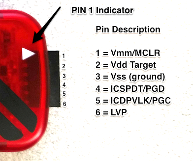
The PICkit 3 is an inexpensive in-circuit debugger. Even cheaper generic versions of the device are available as well. In our experience, both brand-name and generic versions have worked well.
| PICkit 3 | Function |
|---|---|
| VPP (or MCLR) | Programming voltage (usually 13V) |
| VCC or VDD | Power (usually 5V) |
| VSS or GND | Ground (0 volts) |
| ICSPDAT \ PGD | Data – usual port and connection RB7 (PGED) |
| ICSPCLK \ PGC | Clock – usual port and connection RB6 (PGEC) |
| PGM – LVP | Low Voltage Programming – usual port and connection RB3/RB4 |
When attaching the PICkit 3 to the circuit board for debugging, it is not uncommon to find an associated header on a circuit board for the PIC ICSP. An example of this is shown below:
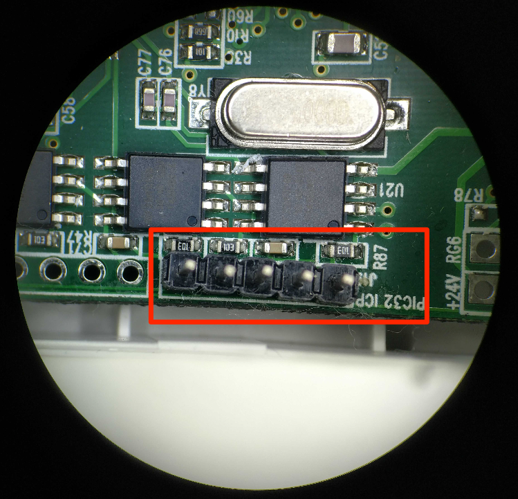
It is also important to assume the ICSP header may not be pinned out as expected, meaning just plugging the PICkit 3 in may not have the expected results. We recommend validating the pinout first. This is best done using the datasheet for the MCU and a multimeter set on continuity to ring out the ICSP header to the actual pins on the chip.
In this example, using the datasheet for the PIC32MX695F512H MCU and a multimeter, we discovered that the header pinout is for the MCU’s ICSP, but its pin layout was not in the correct pinout order to connect directly, as shown below:
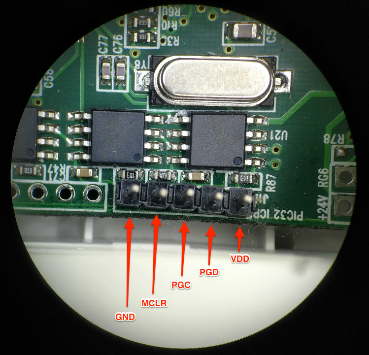
As you can see, it is helpful to always double-check pinouts before attaching any debugger or analyzer to a circuit board. It will save you many headaches down the road and could help prevent damage to affected components. Also note that pin 6 PGM – LVP on the PICkit 3 is not used. This pin is only needed when programming certain MCU devices, and from what I understand is never needed when reading the flash memory.
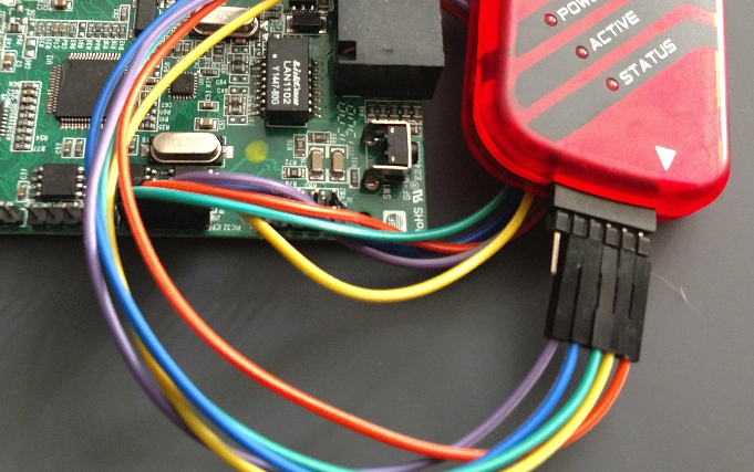
Once the PICkit 3 is successfully attached to the target device, you will need to download and install the MPLab X IDE software available from Microchip. Once installed, it is time to extract the firmware from the MCU.
Open the MPLAB X IDE software and create a new project. You can use the defaults for Category and Project Type. When prompted to select a device, select the Family and the device type being tested. In our example, we used the following:
- Family: 32-bit MCUs (PIC32)
- Device: PIC32MX695F512H
When prompted to select your tool, pick the debugger being used (in our case, the PICkit 3). In the next step, you will need to select Compiler for extracting firmware. You won’t need this, but it’s required to set up a project. Select what is available, or if you’re using this tool for the first time, you may be required to download a compiler. The final step is to give your project a name and select Finish.
At this point, you should be ready to read memory from the MCU. This is done by selecting the icon pictured here:
Then, select Read Device Memory.
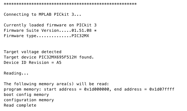
If properly set up and connected, the PICkit 3 status light should begin blinking red and you should see the following information within the MPLAB application, followed by a prompt to save the file:
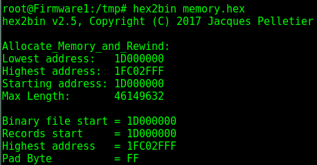
When saving a file, it will be saved as an Intel Hex file type. To be able to examine and test the firmware further, you will need to convert it to a binary file type. This can easily be done using the Linux application hex2bin, as shown below:
Once it is converted to a binary, you will be able to do further testing against the firmware and use other applications such as Binwalk to extract data.
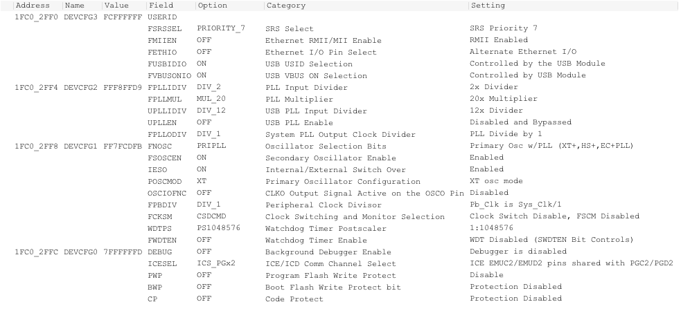
We also recommend exploring the features of MBLab X IDE. For example, once firmware is extracted, look under the configuration bits menu. This will show you the chip’s configuration and security settings.
Check back next week for the fourth and final part of this series, which will go into detail on Texas Instrument RF microcontrollers.