When working on embedded hardware, there is often a need to connect into the printed circuit board (PCB) for testing. This typically requires soldering very fine wire (often 30- or 40-gauge wire) under a microscope to very small test points on PCB before real testing can take place, which can be very tedious and time-consuming.
So, what solutions are available to help make this easier? While there are products on the market that can help by allowing you to attach probes to articulated arms, those commercial systems can unfortunately often run into the thousands of dollars range. There are also some do-it-yourself solutions in which similar, smaller-scale test jigs can be created using 3D printers. For example, several of my fellow colleagues at Rapid7 have used Thingiverse printer data to create a couple, and they are used on a regular basis with great success.
These 3D-printed PCB test probe units appear to be very cost-effective and have come in handy many times, but the biggest issue I hear from coworkers is that the articulated arms are not 100% stable and it can sometimes be difficult to keep them landed on the test spot on the circuit board if they’re bumped while other arms are adjusted.
With that in mind (and combined with a need for a fun after-hours project due to no travel during the COVID-19 pandemic), I went on a search to see what it would take to build a more stable, professional-scale PCB test jig on my own by sourcing parts online.
Since articulated arm stability was the biggest issue, my first challenge was locating articulated arms that were solid, stable, and affordable. Amazon was the easiest and quickest place to track down parts, so I jumped on there, searched around, and ended up purchasing the following articulated arm for testing. As you can see in the image, these arms are designed with a magnetic base and were originally designed for holding measurement gages.
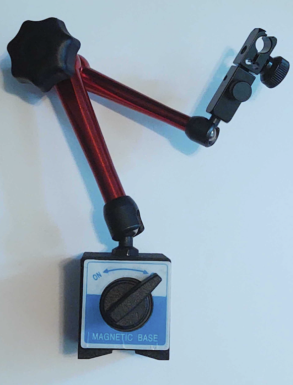
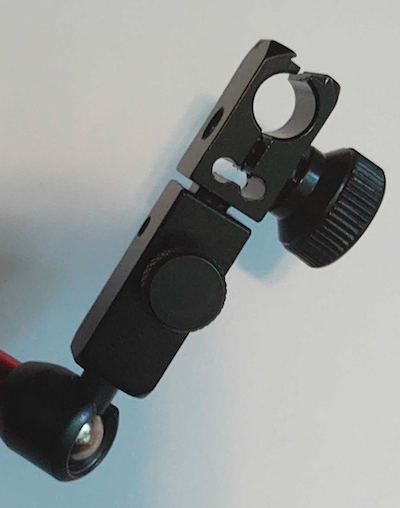
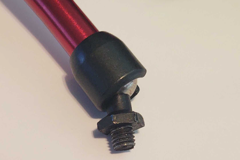
After a quick examination, I determined these can easily be adapted for my needs by removing the magnetic base. The threaded lug at the base of the articulated arm is 5/16 X 18 NC. This information will come in handy later when we need to mount the arms on the test jig.
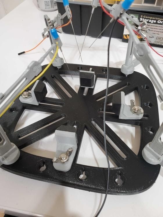
The next part of the puzzle was building the frame. In this case, the parts we found that looked like they would meet my needs for building the frame were the same parts that are typically used for building 3D-printed frame beds with extruded aluminum rails. For this project, I used the following 20mm x 20mm extruded aluminum rails.
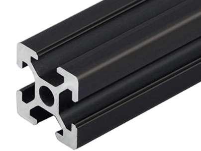
With these aluminum rails, you can build the unit to any size you want. I decided to build my base frame to be 12 x 15 inches so that I could use it on larger-size circuit boards. The 20mm rails can be assembled together using corner brackets and the appropriate size T-nuts and screws.
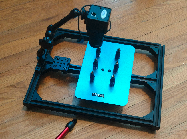
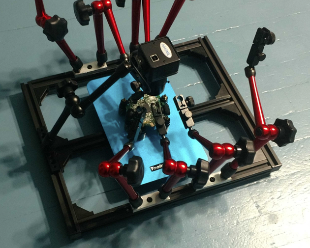
While building out the base frame, I also placed a rail in the center. This rail is a special rail that contains a V groove. This V groove-style rail allows for a moving glide plate to be added. I used this glide plate to mount the magnetic PCB holder to. Also, the camera shown was later mounted to a second glide plate on that same center V groove rail shown in the picture below. Having a movable magnet PCB mount allows the PCB mount to be moved out from under the probes for easier adjustment and setup. I also added rubber feet to the bottom of the base frame to add stability and prevent the unit from easily sliding around.
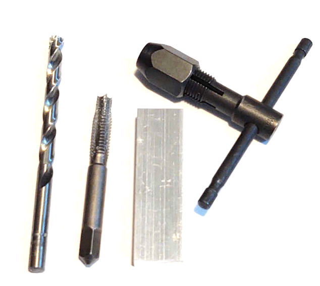
The next phase of the build was to mount the arms along the outer edge of the base frame. During this phase, I was not successful in finding any commercially available mounts that supported the 5/16 x 18NC threads used on the base of the articulated arms. To resolve this problem, I decided to build my own. I acquired four aluminum strip blocks that were ¾ inch wide by 3/8 inch thick by 2.5 inches long. I also purchased a 5/16 x 18NC tap and drill bit set.
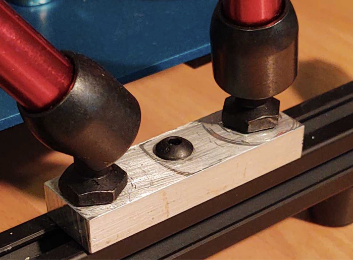
On each of the aluminum strip blocks, I drilled and tapped a hole on each end and also drilled out a mounting hole in the center for attaching the strip blocks using T-nut and screws to the jigs side rails. By having four blocks in this configuration, I was able to add a total of eight arms to my test jig.
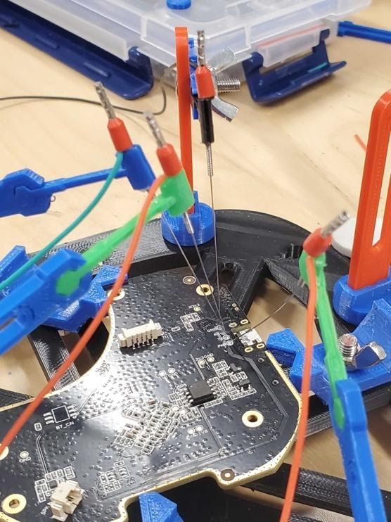
During the final phase of the project, I needed to add probes and electrically connect them to my test equipment. The first step was to select probes that would meet my needs. For this, I purchased a set of automotive test probes with long, sharp needles that could be connected via 4mm banana plugs. To get these probes to properly mount in the articulated arms, I inserted the probe bodies in a short section of rubber tubing. For this, I used a 1/4 ID x 3/8 OD rubber tube.
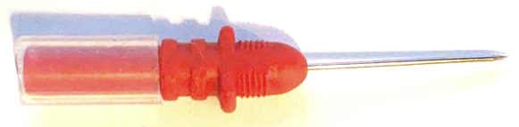
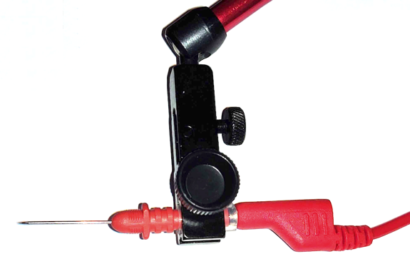
These probes appear to work well, but other probes such as push pins or acupuncture needles could also be adapted for use and would also make for good options.
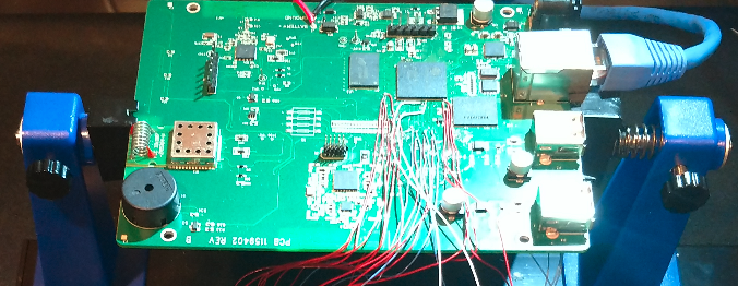
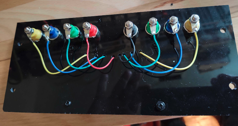
The second step was to create a solution for connecting my test equipment. I wanted a neat, organized setup that allowed the probes to be able to connect via banana plugs cables to a landing spot for connecting my test equipment. For test equipment, I typically end up using jumper wires and breadboards with 2.54mm headers for connecting test equipment to PCBs. So, the solution was to combine both of these. To do this, I purchased a ¼ inch thick black acrylic panel. I then attached a breakout board with color-coded 2.54mm headers and also added banana plugs, and finally soldered all the needed connections together, as shown in following images:

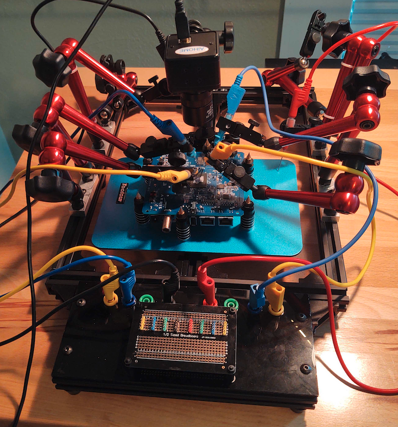
From here, I assembled a frame using the same 20mm x 20mm extruded aluminum I used on the base frame, then attached the acrylic panel to that and attached it all to the front edge of my PCB test jig.
Once it was assembled, I stood back and basked in its glory. It came out amazingly well.
So, for those interested in building a similar test jig, here is the parts list I used to build this PCB prob jig (not including the tools I used). The following parts list is linked to Amazon for identification purposes.
- Automotive Pin Probes
- Banana Plug 4mm 39"
- Banana Plug 4mm 20"
- Acrylic 1/4" Sheet
- Magnetic Adj. Indicator Stand
- Alum. Flat bar "3/8X3/4"X2.5"
- Magnetic PCB Circuit Board
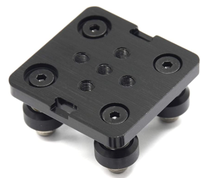
- Small rig Cheese Plate
- 10pcs 4mm Banana Socket
- Tubing 1/4"(ID x 3/8”OD
- 2020 V-Slot Aluminum Extrusion
- Anti-Vibration Rubber feet
- M5 x 8 mm Hex Screws
- M5 Slide in T Nut
- Aluminum Corner Brackets
- 20x20mm Extrusion End Caps
- Small V-Wheel with Plate
- 2020 Anodized 400mm Rail
- Black Articulating Friction Arm
- Colored 2.54mm Headers
- M3 Male Female Nylon Standoff
- Solderable Half-Sized Breadboard
In terms of cost, I am sure that some of these parts could have been cheaper given a little more legwork and research. If you’re looking to reduce your cost, I’d recommend teaming up with someone else who wants to build a probe jig, since parts can wind up being less expensive when bought in bulk. Also, I found that I often received more parts than I needed, such as screws, T-nuts, corner brackets, and rubber feet. So, by teaming up, you can also reduce the number of leftover parts.
Finally, I would recommend being creative. Just because I used these parts doesn’t mean you have to. There are so many options available, so try to be as creative as you can, and if you do find alternate parts, let me know what you tried out on Twitter!