
In our last post, we discussed how we set up Rapid7's hands-on exercise at the Defcon 29 IoT Village. Now, with that foundation laid, we'll get into how to determine whether the header we created is UART.
When trying to determine baud rate for IoT devices, I often just guess. Generally, for typical IoT hardware, the baud rate is going to be one of the following:
- 9600
- 19200
- 38400
- 57600
- 115200
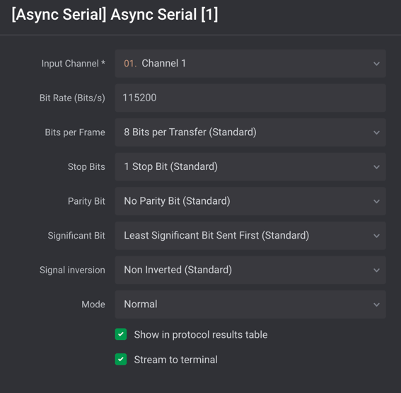
Typically, 115200 and 57600 are the most commonly encountered baud rates on consumer-grade IoT devices. Other settings that need to be made are data bits, stop bits, and parity bits. Typically, these will be set to the following standard defaults, as shown in Figure 5:
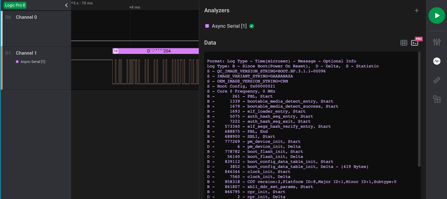
Once all the correct settings have been determined, and if the test point is UART, then the decoder in the Logic 2 application should decode the bit stream and reveal console text data for the device booting up. An example of this is shown in Figure 6:
FTDI UART Setup
Once you've properly determined the header is UART and identified transmit, receive, and ground pins, you can next hook up a USB to UART FTDI and start analyzing and hacking on the IoT device. During the IoT Village exercise, we used a Shikra for UART connection. Unfortunately, the Shikra appears to no longer be available, but any USB to UART FTDI device supporting 3.3vdc can be used for this exercise. However, I do recommend purchasing a multi-voltage FTDI device if possible. It's common to encounter IoT devices that require either 1.8, 3.3, or 5 vdc, so having a product that can support these voltage levels is the best solution.
The software we used to connect to the FTDI device for the exercise at Defcon IoT Village was GtkTerm running on an Ubuntu Linux — but again, any terminal software that supports tty terminal connection will work for this. For example, I have also used CoolTerm or Putty, which both work fine. So just find a terminal software that works best for you and substitute it for what is referenced here.
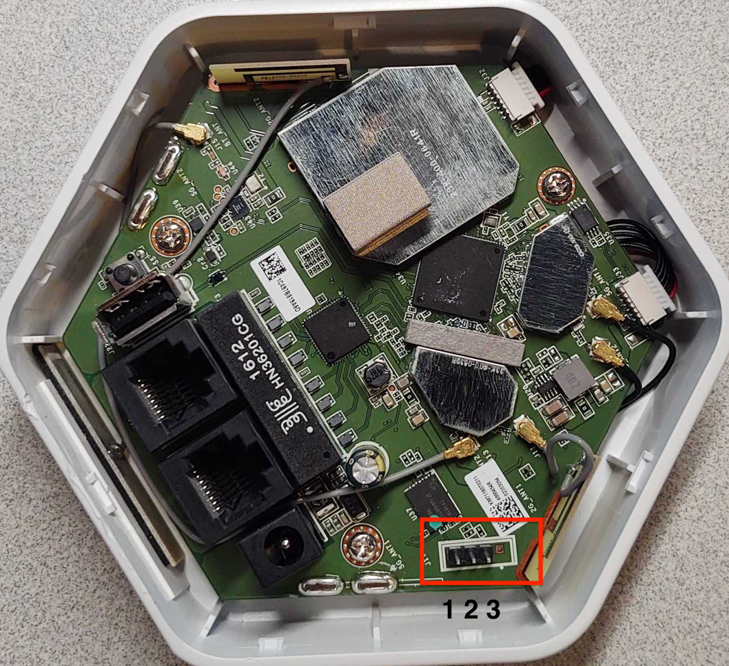
The next step is to attach the Shikra (pin out) or whatever brand of FTDI USB device you're using to the UART header on Luma (Figure 7) using this table:
| Shikra Pins | Luma Header J19 Pins |
|---|---|
| Pin 1 TXT | Pin 2 RCV |
| Pin 2 RCV | Pin 3 TXT |
| Pin 18 GND | Pin 1 GND |
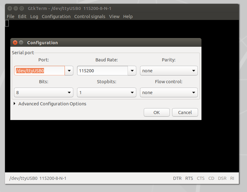
Once the UART to USB device is connected to the LUMA, double-click on the GtkTerm icon located on the Linux Desktop and configure the application by selecting Configuration on the menu bar followed by Port in the drop-down menu. From there, set the Port (/dev/ttyUSB0) and Baud Rate (115200) to match the figure below (Figure 8), and click OK.
Once configured, power on the LUMA device. At this point, you should start to see the device's boot process logged to the UART console. For the Defcon IoT hacking exercise, we had preconfigured the devices to disable the console, so once we loaded U-boot and started the system kernel image, the console became disabled, as shown in Figure 9:
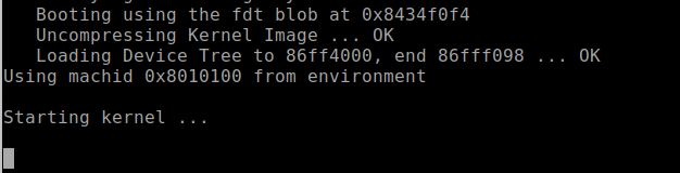
We made these changes so the attendees working on the exercise would experience a common setting often encountered, where the UART console is disabled during the booting process, and they'd have the chance to conduct another common attack that would allow them to break out of this lockdown.
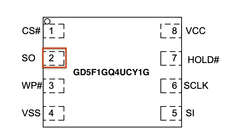
For example, during the boot sequence, it's often possible to force the device to break out of the boot process and to drop into a U-Boot console. For standard U-Boot, this will often happen when the Kernel image is inaccessible, causing the boot process to error out and drop into a U-Boot console prompt. This condition can sometimes be forced by shorting the data line (serial out) from the flash memory chip containing the kernel image to ground during the boot process. This prevents the boot process from loading the kernel into memory. Figure 5 shows a pin-out image of the flash memory chip currently in use on this device. The data out from the flash memory chip is Serial Out (SO) on pin 2.
Also, I would like to note that during the Defcon IoT Village exercises, I had a conversation with several like-minded IoT hackers who said that they typically do this same attack but use the clock pin (SCLK). So, that is another viable option when conducting this type of attack on an IoT device to gain access to the U-Boot console.
During our live exercises at Defcon IoT Village, to help facilitate the process of grounding the data line Pin 2 Serial Out (SO) — and to avoid ending up with a bunch of dead devices because of accidentally grounding the wrong pins — we attached a lead from pin 2 of the flash memory chip, as shown in Figure 11:

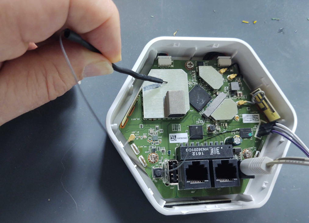
To conduct this “pin glitch" attack to gain access to the U-Boot console, you will need to first power down the device. Then, restart the device by powering it back on while also monitoring the UART Console for the U-boot to start loading. Once you see the U-Boot loading, hold the shorting lead against the metal shielding or some other point of ground within the device, as shown in Figure 12:
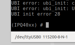
Shorting this or the clock pin to ground will prevent U-Boot from being able to load the kernel. If your timing is accurate, you should be successful and now see U-Boot console prompt IPQ40xx, as shown below in Figure 13. Once you see this prompt, you can lay the shorting lead to the side. If this prompt does not show up, then you will need to repeat this process.
With the LUMA device used in this example, this attack is more forgiving and easier to carry out successfully. The main reason, in my opinion, is because the U-Boot image and the kernel image are on separate flash memory chips. In my experience, this seems to cause more of a delay between U-Boot load and kernel loading, allowing for a longer window of time for the pin glitch to succeed.
Alter U-boot environment variables
U-boot environment variables are used to control the boot process of the devices. During this phase of the exercise, we used the following three U-Boot console commands to view, alter, and save changes made to the U-Boot environment variables to re-enable the console, which we had disabled before the exercise.
- "Printenv" is used to list the current environment variable settings.
- "Setenv" is used to create or modify environment variables.
- "Saveenv" is used to write the environment variables back to memory so they are permanent.
When connected into the U-Boot console to view the device's configured environment variables, the “printenv" command is used. This command will return something that looks like the following Figure 14 below. Scrolling down and viewing the environment settings will reveal a lot about how the device boot process is configured. In the case of the Defcon IoT Village, we had attendees pay close attention to the bootargs variable, because this is where the console was disabled from.
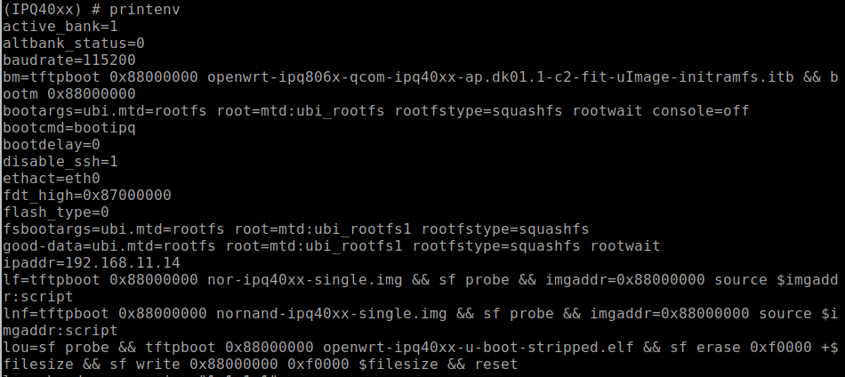
With a closer look at the bootargs variable as shown below in Figure 15, we can see that the console had been set to off. This is the reason the UART console halted during the boot process once the kernel was loaded.

In our third post, we'll cover the next phase of our IoT Village exercise: turning the console back on and achieving single-user mode. Check back with us next week!