This blog is part two in a four-part series on hardware hacking for the security professional and researcher. Click here to check out Part 1, which covers Atmel microcontrollers.
In this blog, we will conduct another firmware extraction exercise dealing with the Nordic RF microcontroller (nRF51822). To be able to gain access to the firmware on nRF51822, we will access the controller using Serial Wire Debug (SWD).
SWD is a common two-pin JTAG debug interface most often found on small form-factor MCUs:
- SWDIO
- SWCLK
For this example, we will use the following tool, application, and datasheet:
The Segger J-Link debugger is a professional JTAG device and can be expensive—starting at nearly $400—but for not-for-profit educational purposes, Segger does make available an EDU version with some limited functionality, for about €50.
Our target device today is a Bluetooth Low Energy (BLE) tracking device running a Nordic nRF51822 MCU. This tracking device is typically used to find your lost keys.
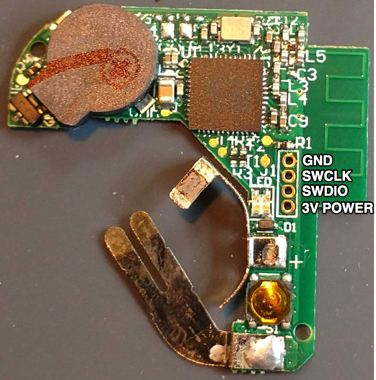
The nice thing about this device is that it appears to have a location for a four-pin 1.27 mm header. We will need to ring out this header to determine whether it connects to our SWD debug on this chip. First, we will need to download the datasheet for the nRF51822 and determine the locations of the following pins. Then, we can use a multimeter set on the continuity check to trace out the pins to the header pins:
- SWDIO
- SWCLK
- VDD = 3v Power
- VSS = Ground
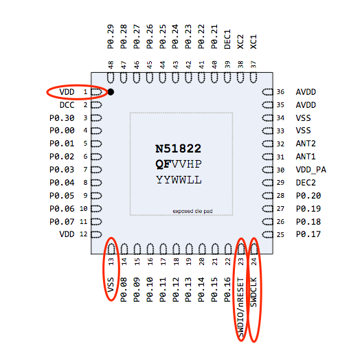
Using the above datasheet pinout and the multimeter, we successfully traced out the necessary SWD connection to the header, as shown below
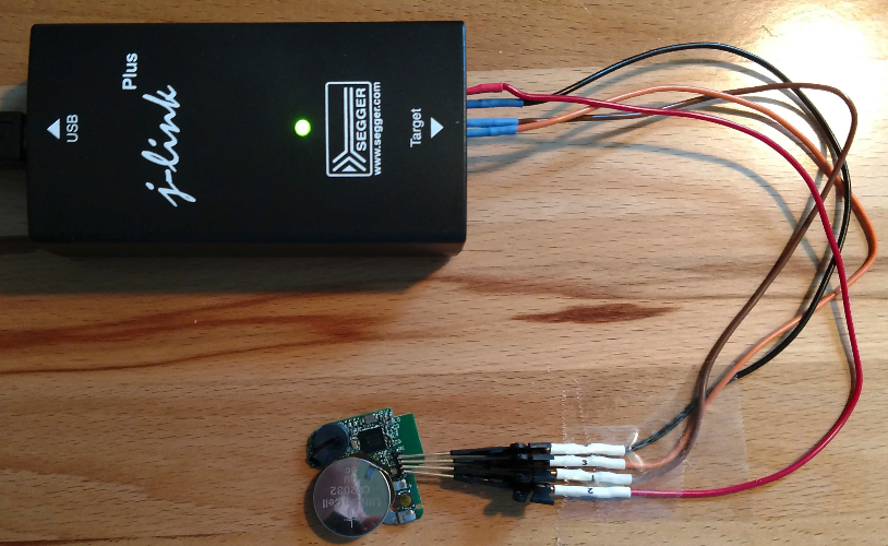
The next step is to solder headers onto the circuit board and connect the device to the Segger J-Link SWD using the following arrangement:
| Tracker | J-link |
|---|---|
| Ground | Pin 4 GND |
| SWCLK | Pin 9 SWCLK |
| SWDIO | Pin 7 SWDIO |
| 3V Power | Pin 1 VTref |
In this example, we used some small clips to connect the J-Link to the headers on the circuit board. It is also important to ensure the device has sufficient power. This simple device is powered by a common three-volt coin cell battery.
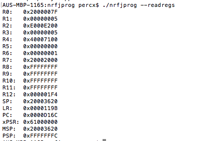
Once you’re connected and the J-Link is plugged into your host USB, the next step is to install the nRF5 Command Line Tools. This software is available for Windows, Linux, and macOS. The version we are using is for macOS. Once downloaded and extracted, you can change directories into the extracted archive folder and run the command-line application nRFJPROG. Here is an example command to read the MCU’s registries:
./nrfjprog --readregs
Next, we can use the command-line application to also read and write other key segments of the device’s memory. We recommend examining the other arguments of the nrfjprog application, which can be listed by running this command:
./nrfjprog --help
Here is an example command to read the MCU’s flash and output it to a file:
./nrfjprog --readcode dump_nRF51822.hex
Once the flash is extracted, it will need to be converted to binary. This can be done with the hex2bin application using the following command:
hex2bin dump_nRF51822.hex
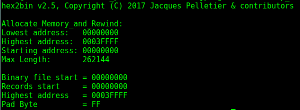
This command will convert the intel hex file (dump_nRF51822.hex) to a binary file format (dump_nRF51822.bin) for further testing and examination.
Be sure to check out the other blogs in this series here: